Deatiled instructions about the installation of cables onto pipelines are in the brochure Instructions for the installation of heating cables. In addition, there is a connection manual enclosed with each connection and termination set.
Laying and connection of heating cables
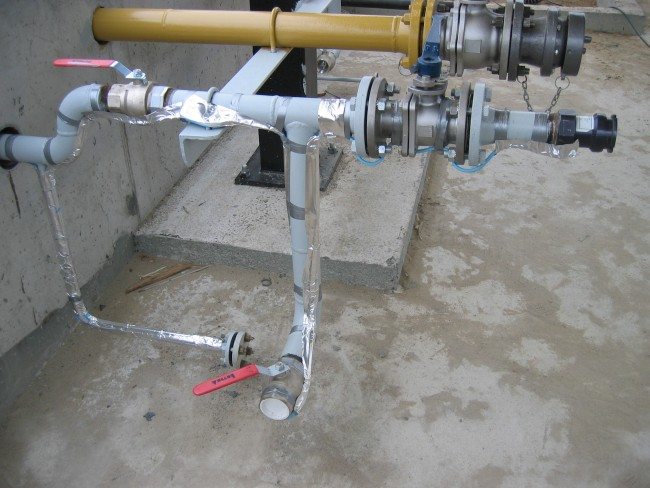
The pipeline is usually treated lengthwise with the heating cable. If the capacity requirements are higher, it is better to use two or more parallelly layed cables along the pipeline. Wrapping the pipe with the cable is seldom used, because of its complexity.
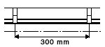
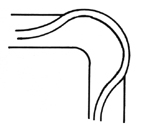
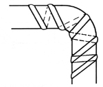
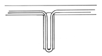
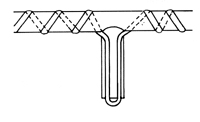
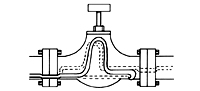
The heating cable is fixed to the pipeline by means of the FX/PE polyethylene adhesive tape or the FX/FG glass-textile tape by enwinding it in cca 30cm intervals. For better heat transfer particularly with plastic pipes, it is good to seal up the heating cable lengthwise with an the FX/AL aluminium adhesive tape. Pipeline arcs and bends are treated on the outer side. For flanges, fixtures, supports, hangers and other places with higher heat losses, we leave out loops, which are wrapped around the treated device in a way that makes its repair or replacement possible without disassembling a bigger part of the heating cable. Shorter pipeline branchings are also treated with loops.
Ending of heating cables
Heating cables are ended by using connection and termination sets. It is necessary to perform the heating cable ending carefully, so that humidity cannot penetrate the cable. A carefully performed ending contributes to a long lifespan of the hetaing cable. Basically, we distinguish two methods of heating cable endings:
- while hot - heat contracting hoses and moulds equipped with an adhesive inside
- while cold - silicone moulds glued with silicone putty.
More about connection and termination sets (illustrational picture of a set)
All sets enabling the connection to the box include the corresponding bushings with oval gaskets. An installation manual is a part of each connection and termination set. The passage of the heating cable through the plating of the insulation is to be protected by an FX/GI insulation bushing. The warning sticker labelled FX/LB, "WARNING, ELECTRO-HEATING", serves to mark a heated pipeline or technological device.
Power supply of heating cables
Heating cables are powered by means of a connection box. Usually, the heating cable is installed directly into the box. For environments without an explosion risk FX/JB connection boxes are used, and FX/JBX clamp lockers for environments with an explosion risk. It is convenient to use an FX/JBB stainless steel holder to mount the boxes to pipelines. It can be used not only for FX/JB and FX/JBB boxes, but also for EBERLE, ZUPO and ZPA Ekoreg thermostats. The boxes can serve not only for the connection of the powering voltage, but also to branch the heating cables. It is thus possible to create a branched heating system following the arms of a certain pipeline. The only limitation is the overall maximum length of a heating cable powered from one place. In some cases it can be convenient to extend the heating cable with a cold supply - a cable with plastic or silicone insulation. The FS/KIT/1,2 a FT/KIT/1,2 universal kits serve for this reason.
The powering switchgear must include a calculated safeguard. With cables with a constant capacity, it is based on the capacity and length of the cable. In the case of auto-regulating heating cables, the starting current from the catalogue, multiplied by the cable length is the decisive issue. All heating systems for pipelines and technological devices should be protected by a circuit-breaker for 30mA. Furthermore, the switchgear can contain a regulation.